1 What Systems Engineering Is
Chapter 1
The label “system” is applied to a vast number of objects in our world. Most people think a system is “something that does stuff.” Simple, but accurate. This could be a device (airplane) or an organization (business). The stuff that it does is all that concerns the user, not how the system does it. I bet your mom is satisfied that her refrigerator cools things but doesn’t spend time thinking about how it’s done. This focus on what a system does is okay if you don’t have to design it. However, design engineers must have a better definition of what the system should do before designing the product. This definition is created by the systems engineer and communicated to the product designers through a set of requirements. This creates a set of constraints that bound the product solution. The methods and tools necessary to design the system are contained within the systems engineering process.
Say your company designs motorcycles. You hear that the demand for efficient transportation in an emerging country is shooting up. This sounds like a business opportunity, so you proceed to research why efficiency is needed, what other capabilities are needed, and what the logistics limitations are. The answers provide the basis for your motorcycle design concept. The concept design leads to design requirements followed by development of a system architecture to complete the system design. You hand off this package to the product designers who come back with a prototype motorcycle. The motorcycle is shown to meet the system requirements, resulting in a product ready for production and sales. Summed up, this means that systems engineering is all about defining needs for a product, defining requirements to satisfy those needs, and structuring the product for the design engineers.
1.1 Definition of a System
You will find many definitions of a system as you acquire more exposure to the books, guidelines, and standards that address the subject. Many of these definitions are written from the viewpoint of specific industries. The National Aeronautics and Space Administration (NASA) has a guideline, the Department of Defense (DoD) has a standard, International Business Machines (IBM) has best practices, and they all communicate the same underlying principles while satisfying their specific industry needs. Because this text deals with the very basics of systems engineering, we will use a direct and simple definition:
A system is a set of interrelated components that function together to satisfy the user needs.
This definition identifies the system’s objective as satisfying the needs of those who use it. The system does this by possessing characteristics that produce the needed functionality. We satisfy this definition by creating a system that has the following:
- Components: The functional parts of the system
These work together to satisfy the user need to produce an effect. The effect is what the system does and not how it does it.
- Characteristics: The structure of the system
The parts that possess the physical attributes and capabilities of the system. These are organized into conceptual blocks (subsystems) that make up the system functionality.
- Relationships: The interaction between parts
The parts (components) must work together to integrate individual tasks to produce the system functionality. These interactions include those within the system as well as those with external entities that support system operation.
1.2 The Systems Engineering Discipline
Systems engineering evolved out of the need to create ever more complex designs in a rapidly evolving technological world. If you were to think about how major products (ships, buildings, aqueducts, bridges, etc.) were designed long ago, you would see that the tools and methodologies were specific to the product and applied by masters of the craft. Shipwrights understood how to design ships by learning the techniques during apprenticeship to a master. This was a generational process that was able to keep up with the slow evolution of ship technology. These were essentially “craft-made” products.
This design model came under pressure during the Industrial Revolution. New technologies were being introduced at an ever-increasing pace. The craftsman way of designing was incapable of keeping up. Their way of handing down design methods through apprenticeship gave way to generalized methodologies of design. These were the tools of specialized engineers (mechanical, electrical, mining, etc.). The tools were both analytical and empirical and were able to evolve along with technology.
The generalization of techniques allowed products to be designed for one application and adapted for new applications. The engineers designing these new products were experimenting with component combinations to find a set that satisfied their need. This worked effectively for many years. You had to know only the components, attributes, and relationships to apply an existing system in a new way. This meant that you could use an automotive engine to drive the propellers on your new flying machine. They were using systems thinking, but the discipline had yet to be defined or structured.
People started recognizing patterns in these evolving systems of products and started to conceptualize these patterns. The concepts then led to the discipline of systems engineering, including the methodologies and tools. We can see this evolution by studying a few pioneers in the development of systems engineering.
Wiener’s (1947) cybernetics principles focused on the self-regulating nature of feedback loops in a system. By recognizing that control system actions are fundamentally the same, he was able to apply mathematics to describe the logical flow of actions in the feedback loop. This innovation provided the means to model the system. An example is the simulation of the flight control system of an aircraft. The mathematical model created to represent the actual aircraft flight controls takes an input to the system, executes the modeled system interactions, and then produces an output. This model could then be used to efficiently evaluate the operation of the control system across a broad spectrum of flight situations.
Bertanlaffy’s (1950) general systems theory introduced the concept of a framework based on the interacting of components within a system. The framework provides conceptual distinctions and organizational ideas to give an overall picture of the item rather than to classify the item within an existing structure. The framework gives us the ability to organize the system in functional terms rather than by the system structure itself. An example is the modeling of a biological system in terms of the relationships between separate entities rather than by simply defining the individual entities themselves.
Boulding’s (1956) general systems theory offered that a hierarchical structure across multidisciplinary fields can integrate the complexities of those fields to achieve greater understanding of the system as a whole, each level incorporating the capabilities of those below. This provided an overarching view of multidisciplinary systems with roots in multiple specialized fields. An example of the melding of one specialty with another is the creation of the biophysics field. Biologists seek to describe the nature of a biological system while physical scientists want to use mathematics to explain how the physical system works. An overarching framework (biophysics) allows the two specialties to integrate the details into a larger understanding of how biological systems function as a system. As Boulding said in an article for Management Science, “General Systems Theory is the skeleton of science in the sense that it aims to provide a framework or structure of systems on which to hang the flesh and blood of particular disciplines and particular subject matters in an orderly and coherent corpus of knowledge.”
Wymore’s (1960) theory of systems engineering conceptualized user needs driving the system design. This has become the ruler against which system acceptability is measured. If the system design is not anchored in a clear set of needs, then the resulting product may end up being unacceptable to the user. An example is a marketplace need for electric-powered vehicles. The need spurs a car company to invest in developing electric drive cars. The resulting system design must ultimately satisfy the marketplace need or the new product will not sell. That is an unacceptable system design.
Checkland’s (1975) soft systems methodologies provided a means to deal with problems that have no formal problem statement. This broadened systems theory into more conceptual realms for problem solving, such as business practices. The move from purely physical applications to conceptual ones greatly expanded the use of systems engineering. An example is modeling hospital operations. Characterizing the organization and interactions of departments provides a basis for analyzing the system operation as a whole. In this way, hospital operations can be optimized as a total system rather than as individual departments divorced from the operation of the others.
The work of these pioneers has shaped the field of systems engineering and given us the fundamental understanding of systems used to develop the methodology and tools for solving complex problems.
1.3 Theory to Standardized Practice
Systems engineering was being practiced in many engineering fields, most notably space programs. However, the practice was not consistent across these fields. The methodology and tools were specific to each field of application. That changed when the DoD etched the practice in stone when they released the standard for Management of Engineering and Technical Programs, MIL-STD-499, in 1974. This document directed that the government and contractors developing new military capabilities must utilize a specific systems engineering practice. The document described the effort as “the management of the engineering and technical effort required to transform a military requirement into an operational system. It includes the system engineering required to define the system performance parameters and preferred system configuration to satisfy the requirement.”
Take, for example, the development of the C5A transport aircraft in the 1960s. The development contract required that Lockheed implement a system management structure for designing the aircraft but also created an independent government systems management structure for oversight. The subsequent development and management of design requirements became an integral part of the design of this complex system. The requirements were very stable throughout the design phases, resulting in a product that it is still useful today. Interestingly there was a design issue with the wing group that drove a redesign mid-program. That issue could be seen as a failure in systems management of the development. In reality, it resulted from the contract incentive structure favoring aircraft empty weight over all other design parameters. This essentially hamstrung the system design team from trading empty weight to gain performance in other areas.
MIL-STD-499B (draft) was intended to replace the original version but was never released. This was due to the migration from government standards to industry standards (Figure 1.1). The move created a void in guiding documentation because businesses that relied on government standards did not have any of their own. Some defined and documented their own best practices. Others relied on new organizations created for the purpose of documenting standards. One such industry standard is the current means by which the practice and language of systems engineering is practiced around the world. This is the Systems & Software Engineering- System Life Cycle Processes standard (ISO/IEC 15288).
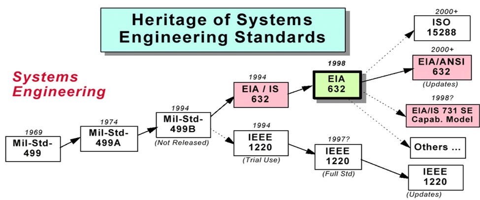
During the migration from government to industry standards a worldwide group dedicated to systems engineering was founded. The International Council on Systems Engineering (INCOSE) is a member organization with the mission of “integrating systems engineering concepts, terminology, and methodologies around the world.” This organization provides the systems engineering discipline with a common language and description of practices. The INCOSE definition of systems engineering is “an interdisciplinary approach and means to enable the realization of successful systems. It focuses on defining customer needs, and required functionality early in the development cycle, documenting requirements, then proceeding with design synthesis and system validation while considering the complete problem.”
1.4 Types of Systems
Classification is a standard practice for any scientific field. By classifying systems, we can get a high-level understanding of the common characteristics found in the many types that exist in the world. The classification method for systems revolves around the identification of three characteristics:
- Naturally occurring or human modified. A natural system has evolved in the world with no human modifications. An example is an ecosystem that has found its own balance and evolves out of environmental necessities. A human-modified system is everything else, including those designed by humans and those naturally occurring systems modified through unintentional interaction with us.
- Physical or conceptual. The physical system is manifested in a physical form. It has dimensions in our world. You can see, touch, taste, or hear it. The majority of what we would identify as systems have this characteristic. By contrast the conceptual system is a symbolic representation of an idea that has no physical existence. I consider software such a system as it is manifested only when loaded into physical hardware. You can’t sense its existence; you can only evaluate the symbolic representation of it.
- Dynamic or static. A dynamic system takes an input, performs a task, and produces an output. It satisfies the user’s need by actively producing the desired outcome from a defined input. The static system does not perform any tasks; it satisfies the user’s need in an unchanging state. A bridge is such an example. It comprises static interrelated components that satisfy the user’s need to drive their car over a river. A bridge would be dynamic if it could raise and lower to allow shipping to pass underneath. In this case the distinction of static or dynamic rests solely on whether the bridge needs to raise and lower (perform a task) or doesn’t.
In reality it doesn’t matter how we classify a system as the methods for designing the system are the same, excluding natural systems, which are hands off to humans. For our purposes we will focus on a “physical-dynamic” system to demonstrate the processes you will be learning. That will hold true until we get to the section on software systems engineering. We will then enter the extremely valuable realm of “imaginary systems” (i.e., conceptual).
1.5 Fundamentals of Systems Engineering
Systems design can be a daunting job given the complexity of many systems. The only realistic way to design an acceptable system is to break the problem down to the simplest parts. The system design is then built one piece at a time by linking these simple system elements. This is done using the core tools in the systems engineering methodology.
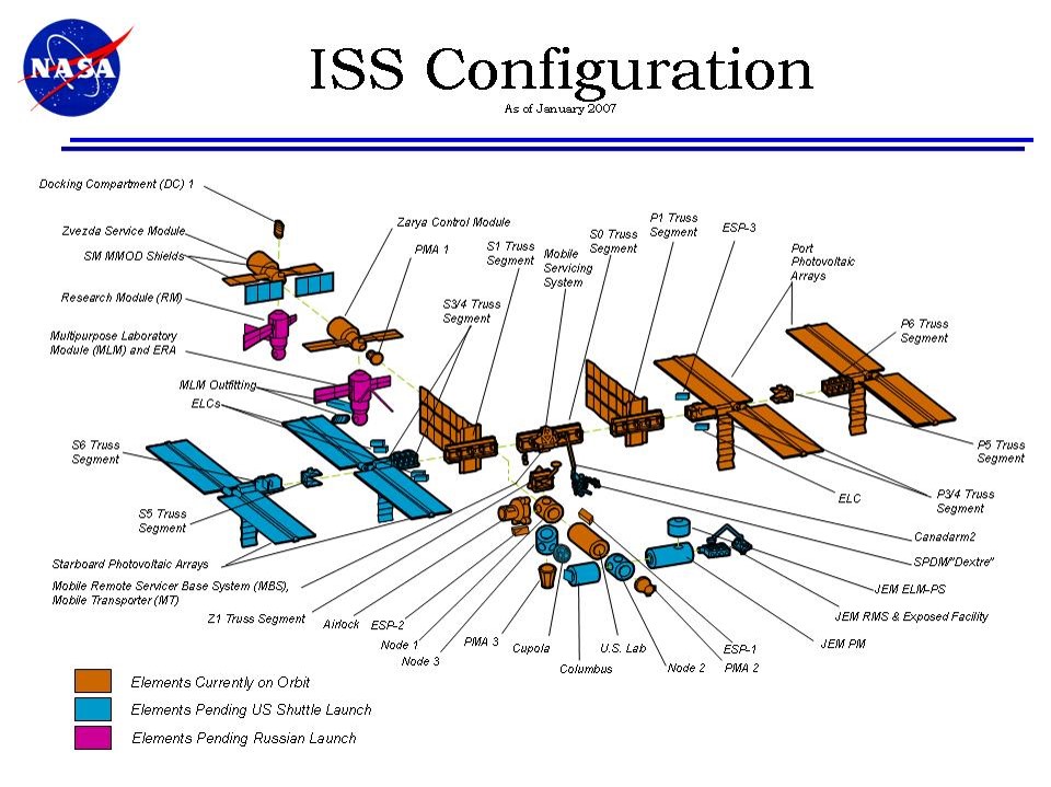
The International Space Station (ISS) is a good example of a complex systems engineering effort. The ISS is a multinational laboratory in space. The development was done by a consortium of parties led by NASA. The system was a combination of new design and integration of existing modules (Figure 1.2). The difficulty for the systems engineer reusing an existing system is that the requirements for the existing system must be used “as is.” That means the new design elements must conform to the existing requirements yet still deliver new functionality.
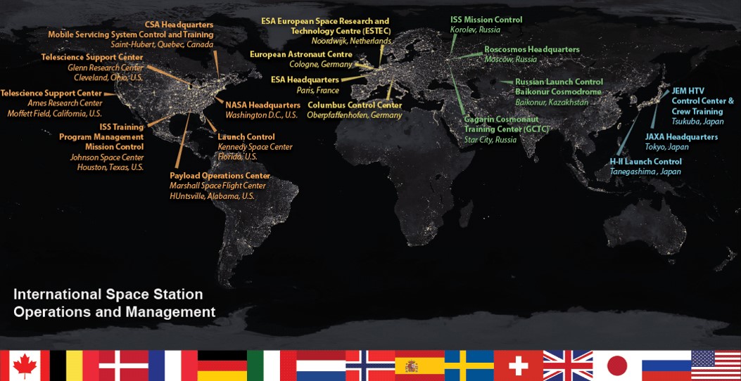
In addition to the physical design challenges, the ISS system was being developed by companies around the world. This required constant communication and detailed documentation (Figure 1.3) to ensure that the individual pieces integrated into a compliant system. Ultimately, the ISS was successfully designed, manufactured, and integrated in space and is still performing its mission. The case study of the systems engineering effort (Reference 7), makes a good read after you learn more about the systems engineering methodology.
1.5.1 Role of the Systems Engineer
The systems engineer has to define the problem to be solved in technical terms and then create a set of constraints for the product designer. They do not dictate the physical design of the product, just the functionality and boundaries of the design. These characteristics are communicated through a set of requirements that designers use in creating the physical product. The handoff of requirements implies a separation between the job of the system engineer and that of the product designer. One is focused on conceptual definition and the other is focused on physical implementation. The truth is that the two work together to understand what technologies are both feasible and desirable in the product while developing the system concept. This requires that the systems engineer maintain big picture perspective while working as an integrated team with the product designer during both concept development and product implementation.
1.5.2 System Boundary
If complex systems are a chain of simple systems (individual system pieces), as Boulding surmised, then why isn’t there just one system in the world? Aren’t all pieces in the world connected in that one universal system? How do you decide that you have chosen the right ones from the universal set to completely define your system? What happens to all the pieces you didn’t include? You have asked some really important questions here, and the answers go to the essence of the system engineer’s job, that is, to add pieces until the system meets the user needs, and then stop. Too many, and the system does more than is really needed, incurring a cost impact. Too few, and it will fail to meet the user needs. Do not mistake this as a statement that there is just one set of simple systems that comprise the right design—far from it. Any number of combinations can achieve the design goal. Rather than finding a singular set of pieces, we define a set that meets the singular criterion of success—a system design that meets user needs with the greatest efficiency.
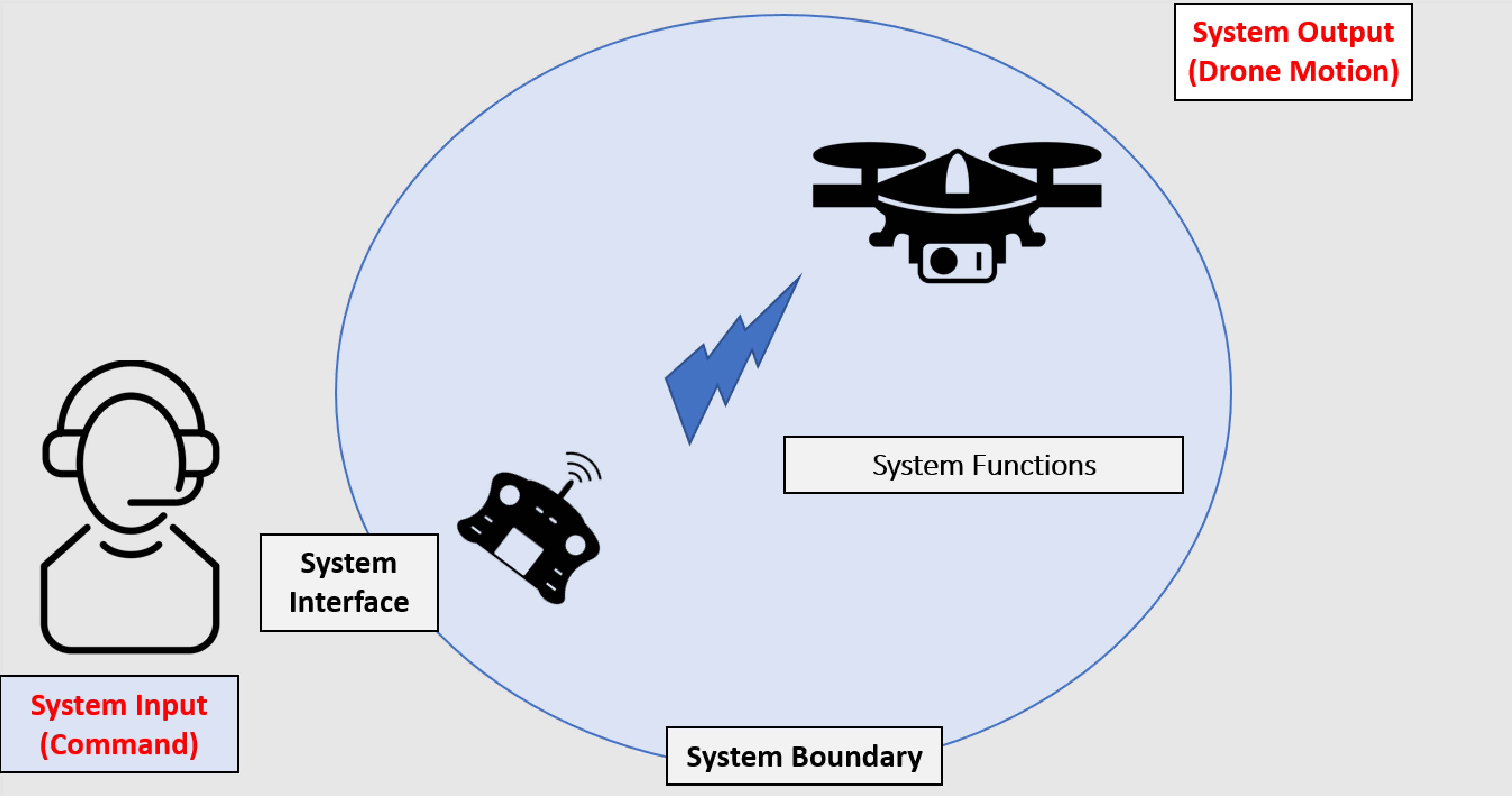
We separate the set we include from those we don’t by drawing a line called the system boundary. This line encompasses the simple systems we want, defining the system functionality we want. All other pieces in the universe are outside the boundary we have just defined. Some of these interact with the system, making them an important part of our design. They either supply an input to our system or they receive an output from our system. Any external system that does not have an interaction with our system is irrelevant and is to be ignored in designing our system.
A drone is a good example of the system functions inside the system boundary and the external systems that interact with the drone. The system boundary diagram in Figure 1.4 depicts a user inputting a command and the system performing functions and delivering a desired output. In this case, the input is movement of a control stick by a pilot. The resulting system output is the motion of the drone. All the functionality necessary to go from input to desired output is captured within the system boundary. This functionality constitutes what the system needs to do. Creating the system boundary is one of the most important steps in the process because it defines the limits of the system functionality and the interactions with the external world.
1.5.3 Systems Design Process
The process of systems engineering is focused on bounding the product design to include only what is necessary to meet the user needs. This involves defining the problem to be solved (with high-level needs) and creating a conceptual system to solve it. A preliminary system design is then developed to define the functionality. Finally, a set of requirements and a structure to constrain the design of the system are written. The product designer uses these requirements to create the physical product from this system design.
An example is a new car. For a company to spend money on a new car design there must be a need for it. This is the problem to be solved by the company. The problem is solved by creating a conceptual design that addresses the need. The conceptual design defines the tasks to be performed by the new car. This set of tasks (functions) is then turned into a set of requirements, which is then used to design the physical car itself.
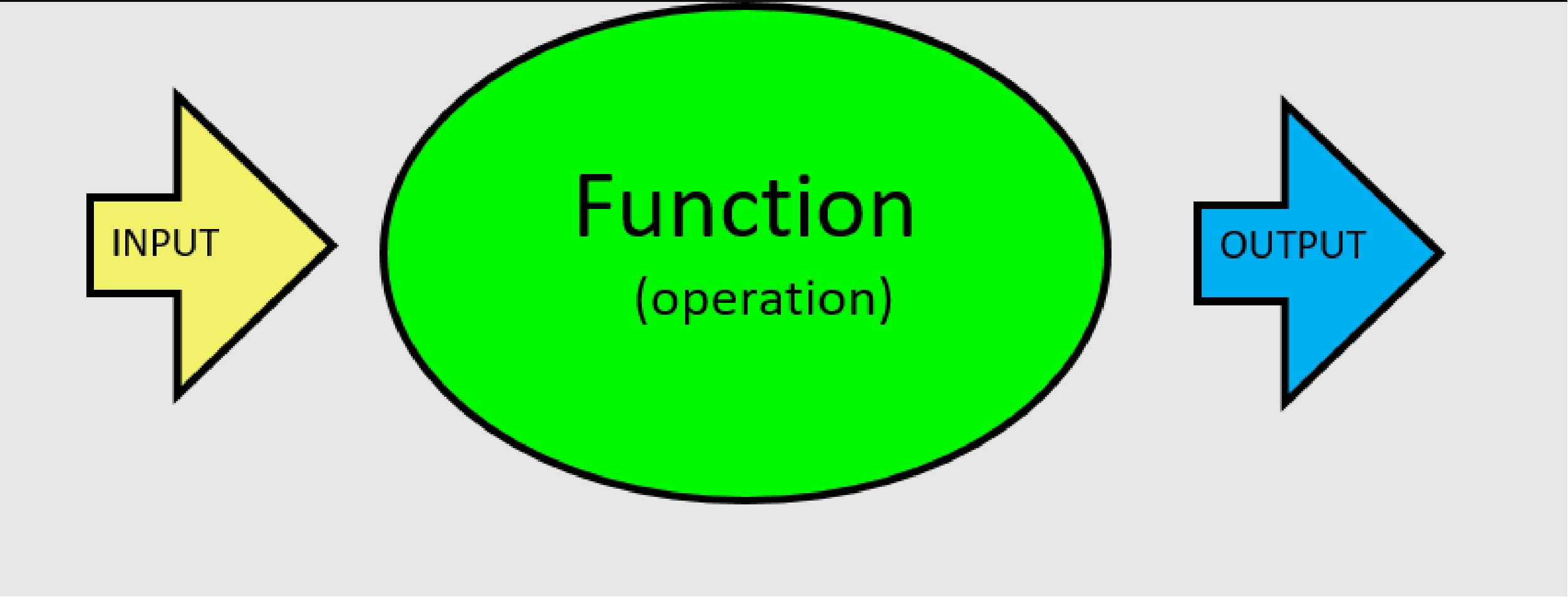
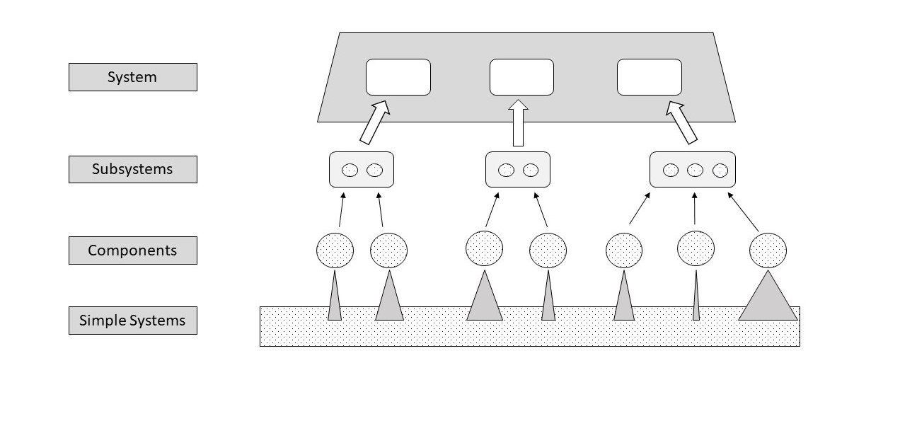
Most problems are complex enough to exceed our ability to visualize the complete system all at once. So, we define functional pieces and integrate them together to define the full system functionality. The simplest functional piece is one that takes in an input, performs a function, and produces an output (Figure 1.5). This represents the basic building block for all complex systems. The output from one piece provides the input to the next. Figure 1.6 shows the structure of a complex system by depicting the hierarchy of simple systems aggregating into larger subsystems until the total system is defined. The process of taking simple pieces and bolting them together into a final system design does not happen in a strictly linear fashion. Many iterations occur along the way. These result from discoveries that represent incomplete knowledge at the outset. This lack of knowledge and subsequent discovery during design is why systems design relies on simple steps rather than an attempt to visualize the complete solution at the beginning.
1.6 System Design Steps
The following is a high-level look at how the systems engineer defines the problem and creates the system solution. Each fundamental step will be described and followed by an example that demonstrates the concept. I will be using the development of an express checkout system for a grocery store through the rest of this book to demonstrate each systems design concept.
- Define the problem and system solution.
- What is the void that a new system will fill, or what improvement will it provide? The answer to this question yields the problem to be solved. A poorly defined problem is unlikely to yield a proper systems solution. Accurately defining the problem allows the systems designer to define what is necessary and sufficient to solve the problem.
- A grocery store is experiencing long waits at their cashier stands, creating a drop in customer satisfaction. These wait times do not repeat at the same times during the week nor persist for the same duration. Adding shifts to have cashiers available to eliminate the wait times has been judged not to be a cost-effective solution. An automated system is needed to provide faster checkout without increasing labor costs. I have named this the express checkout system.
- Identify the stakeholders.
- Who has an interest in the systems design? These are the users, regulators, or impacted parties whose needs must be considered in the systems design. If a group has interests that will not affect the systems design, then they are not stakeholders for your system.
- Certainly the shoppers and businessowners are stakeholders for the express checkout system; these are obvious. Less obvious are the external systems that we interact with such as banks and taxing authorities. Other interested parties are regulators, who write laws constraining the design, and special interest groups that place constraints on the design due to their social influence.
- Determine the stakeholder needs.
- What needs must be satisfied for the system to be acceptable? Needs define the functionality and characteristics that your stakeholders want. Needs must be satisfied by the systems design for the resulting product to be considered acceptable.
- The needs for each stakeholder are extracted from the description of their interest in the systems design. For our express checkout system they will range from business considerations (accuracy, reliability, operating cost, marketing) to shoppers (speed, simplicity, flexibility), to taxing authorities (accurately accounting for tax receipts), and so on.
- Define the system concept.
- What is the functionality of the system? Functionality is the set of operations the system will perform to take an input and turn it into a desired output. This is the groundwork for creating requirements for the product designers.
- The functionality of the express checkout system encompasses all the operations that must be performed. They mostly arise from evaluating the logical steps necessary to satisfy the shopper’s needs, such as the shopper wanting (needing) the ability to pay with cash, debit, credit, or coupons. This translates into a sequence of steps for the system to receive the instructions on how the user wants to pay, to transact that payment, and to produce a receipt detailing the transaction.
- Specify the constraints.
- What requirements are necessary to bound the physical product solution space? The solution space bounds the functionality and physical characteristics for the product designer, thus defining what the product must do and by omission what the product must not do.
- For our system we would write a requirement for every function we identified. For example, the need to pay with a debit card would translate into requirements to “accept instructions,” “read the card,” “process the transaction,” “log the transaction,” and “produce a receipt.” The product designer would have no choice but to design these capabilities into the product, effectively constraining what they can consider in the design solution.
- Create the structure for the design.
- The structure defines the physical subsystems and relationships necessary for an efficient product design. The structure is called an architecture. The process of developing the architecture involves defining subsystems and assigning system functionality to each.
- The processing of a debit card transaction would require physical subsystems to “accept shopper instructions,” “read the card,” “communicate with the bank,” “store the data,” and “print a receipt.” Implied are the subsystems required to “power the system” and “control the execution” (computer and software).
- Document the system.
- Write down the requirements in explicit technical terms. This is done by creating a document (specification). A specification is the primary means for dictating the system design constraints to the product designer.
- Communicate the design concept with defined artifacts (diagrams and tables). The artifacts provide a tangible expression of the system in a standardized format. These artifacts provide the means to explain the system design to others. This is essential not only for defining the product design but also for preserving the thought process for those who will modify the system in the future.
- Certify the design.
- After the product is designed, it is then tested to verify that all requirements are met. The test results either demonstrate product compliance to the requirements or identify “shortcomings” in the design. If there are shortcomings, the systems engineer works with the product designer to implement corrective actions. Once the design is shown to meet all its requirements, the systems engineer certifies the design to be compliant. At this point the design is complete and moves to production.
All the methodologies and tools to perform these activities will be covered in the coming chapters. As Margaret Hamilton famously said in the Wizard of Oz, “All in good time, my pretties. All in good time.”
Recommended Readings
Hallam, C. R. A. (2001, October 16). The art of managing complexity. http://web.mit.edu/esd.83/www/notebook/syseng.doc
NASA. (2009, January 18). The art and science of systems engineering. https://www.nasa.gov/pdf/311199main_Art_and_Sci_of_SE_SHORT_1_20_09.pdf
Image Credits
Fig. 1.1: Florida Department of Transportation, from "A Process Review and Appraisal of the Systems Engineering Capability for the Florida Department of Transportation (FDOT),” p. 8. Copyright © 2003 by Florida Department of Transportation.
Fig. 1.2: Source: https://www.nasa.gov/images/content/166624main_iss_config_012007.jpg.
Fig. 1.3: Source: https://www.nasa.gov/sites/default/files/thumbnails/image/ops_map.png.
Fig. 1.4a: Copyright © by ahmad (CC BY 3.0) at https://thenounproject.com/search/?q=2090113&i=2090113.
Fig. 1.4b: Copyright © by ahmad (CC BY 3.0) at https://thenounproject.com/search/?q=2090093&i=2090093.
Fig. 1.4c: Copyright © by Andrei Yushchenko (CC BY 3.0) at https://thenounproject.com/search/?q=3035862&i=3035862.
IMG 1.2: Copyright © by ahmad (CC BY 3.0) at https://thenounproject.com/search/?q=2090113&i=2090113.
IMG 1.3: Copyright © by ahmad (CC BY 3.0) at https://thenounproject.com/search/?q=2090093&i=2090093.
IMG 1.4: Copyright © by Andrei Yushchenko (CC BY 3.0) at https://thenounproject.com/search/?q=3035862&i=3035862.
IMG 1.5: Copyright © by HAMEL KHALED, DZ (CC BY 3.0) at https://thenounproject.com/term/satellite-dish/3617970/.
IMG 1.6: Copyright © by H Alberto Gongora, CO (CC BY 3.0) at https://thenounproject.com/term/airport/2892634/.
Video Tutorial – System Boundary